BPMN Diagrams are usually displayed as two-dimensional images. A top-down view of the process, that focuses on readability and is practical for day-to-day work. Those of you who were at BPMCon 2017 will probably remember the interactive experience “Be A Token” where you could walk around in a BPMN process in virtual reality. This blog post describes how the 3D rendering of bpmn processes is built with JavaScript using bpmn-js and A-Frame.
If you missed BPMCon or did not get the chance to play it in virtual reality, there is an online version of “Be A Token” which can be played in the browser.
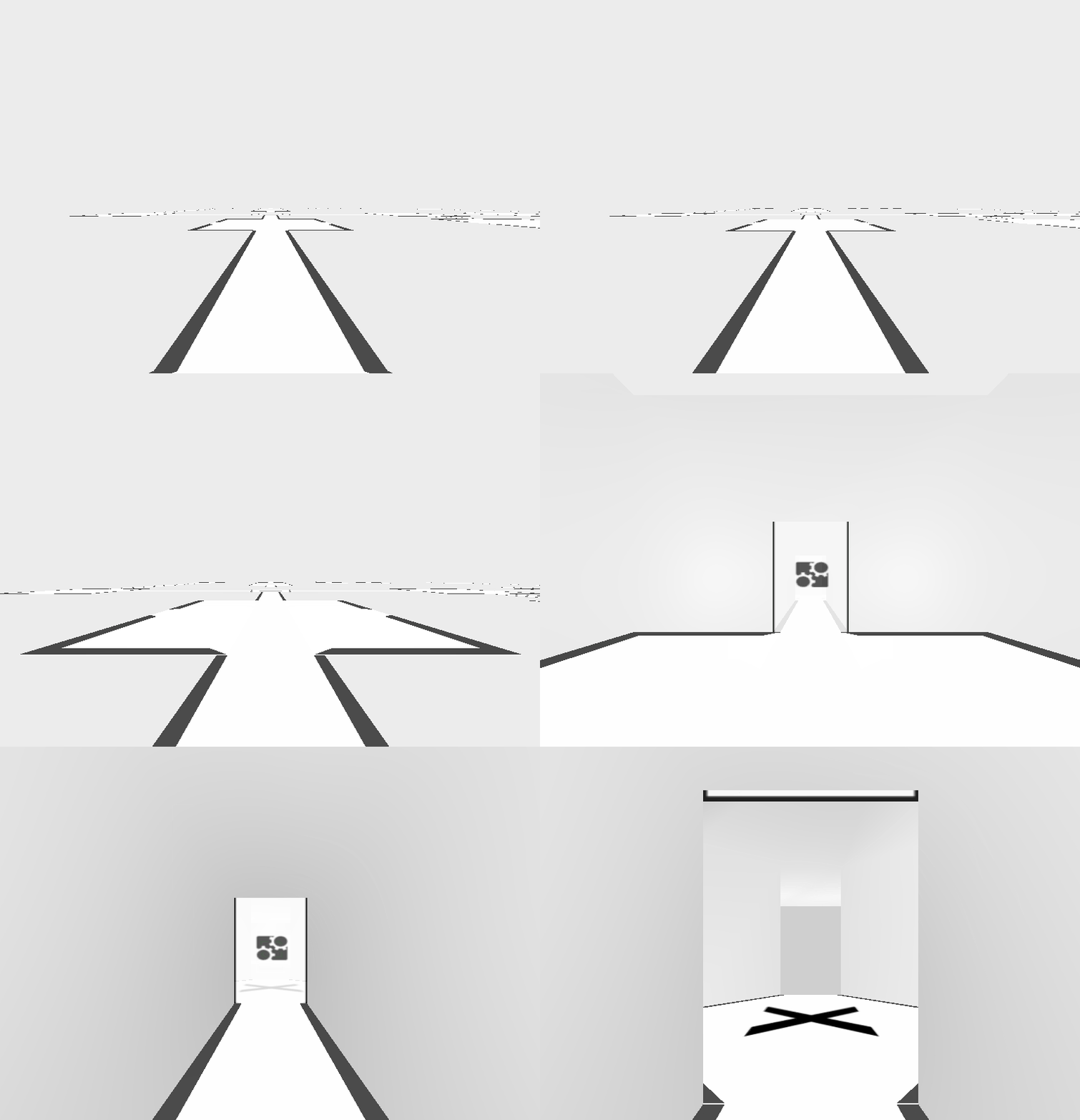
Getting a JavaScript representation of the process
A BPMN file is a XML file containing information about all the elements, their properties and how they should be displayed. JavaScript is not very good at dealing with XML directly, so before working with the file, it needs to be converted into the JSON format.
Fortunately, the bpmn-js library can do that. The primary focus of this library is to render a bpmn process, but to do so it creates a JavaScript representation of the underlying logical structure of the process. This representation can be used to create a 3D model of the process. First, the model is imported as described on the bpmn-js GitHub page:
const BpmnViewer = require('bpmn-js');

const xml; // my BPMN 2.0 xml
const viewer = new BpmnViewer({ container: document.createElement('div') });

viewer.importXML(xml, function() {
  // our rendering takes place here
});
Using the elementRegistry, the elements of the model can be accessed in order to create a 3D representation of them:
const elementRegistry = viewer.get('elementRegistry');

elementRegistry.forEach(element => {
  if(element.businessObject.$instanceOf('bpmn:Task')) {
    renderTask(element);
  } else if(element.businessObject.$instanceOf('bpmn:Gateway')) {
    renderGateway(element);
  }
  //...
})
The elements themselves have x, y, width and height properties which contain all the information needed to create a 3D representation.
About 3D rendering
A three-dimensional model in the context of computer graphics consists of vertices and faces. A vertex defines a position in space and has three coordinates: x, y and z. A face is a triangle, connecting three vertices to a surface.
For example, a cube would consist of 8 vertices (one for every corner) and 12 faces (6 sides and each side can be represented by 2 triangles). The next sections describe the construction of the 3D model for different BPMN elements.
Sequence Flows
Sequence flows are usually represented as lines with an arrow pointing from a source to a target activity. This line can contain multiple corners. In the bpmn file, this is specified by a waypoints array, which contains all points where the sequence flow line changes direction plus the start- and endpoint of the sequence flow. A graphical representation would look like this:
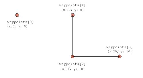
A sequence flow is a single line and does not specify a width. When rendering a sequence flow in 3D, in order to move “through” the sequence flow, it needs to have some width so that it can be represented as a hallway. To achieve that, the sequence flow is split into multiple straight segments which are joined at the waypoints in a separate step.
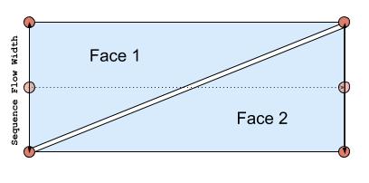
Creating a hallway for a straight segment is easy: Take the start and endpoint and move them parallel to the original line in either direction for a specified distance depending on how wide the hallway should be. The newly created vertices can be connected as two faces to form the floor of this sequence flow segment hallway:
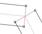
Whenever a sequence flow is not a straight line, multiple instances of those hallway segments are created that need to be merged to form one continuous hallway. At the waypoint where the sequence flow changes direction, the two vertices that define the hallway do not align. To fix that, a new vertex which is between the two original vertices and has the same distance to the hallway center is created. This creates a closed continuous hallway for the sequence flow. The following images illustrate this process:
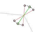
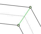
This algorithm creates the vertices for the floor of the sequence flow. To create walls and a ceiling, every vertex is copied and the z-Position of each copy is set to the desired height of the sequence flow hallway. You can find the JavaScript implementation that maps the original waypoint array to a list of vertices and the construction of the final vertices and faces.
Now that 3D representations for sequence flows are done, let’s look at tasks:
Tasks
Tasks are usually represented as rectangle with the task name written on it. An appropriate translation to 3D would be a room with the task name written on the floor. A basic room would just be a cube the player can stand inside of. However, tasks are connected to sequence flows, there has to be holes in the walls that the player can use to enter and leave a task-room. This requirement leads to a more interesting configuration of vertices and faces. This is a single wall with the position of its vertices and faces of a task in “Be A Token”:
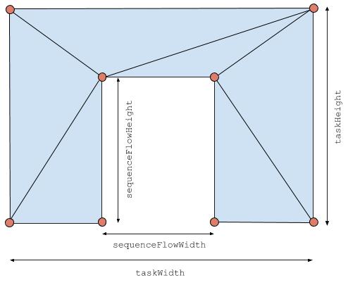
The floor and ceiling of the task room can just re-use the vertices created by the four walls.
Note that the placement of the hole in the wall for the sequence flow is always in the same place. That means that the connection to a sequence flow also always has to be in the same place. This works well with the manhattan-layout, where only 90° angles are allowed. A sequence flow connecting to the corner of a task will not be rendered correctly. For “Be a Token” this is not a problem as the levels can be designed accordingly.
When the geometry of the wall is generated like described above, the hole in the wall will always be there, even when there is no sequence flow attached. In “Be a Token” this is fixed the same way you might hide a hole in a wall in the real world: By putting something over it. When there is no sequence flow attached, a static image is rendered there, so that the player cannot see through the hole in the wall. If you are curious how this is done, you can find the code here.
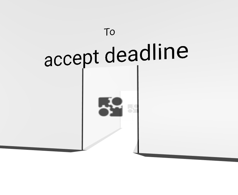
The same mechanism can be used to implement a door: When a sequence flow is attached to a side of a task, a semi-transparent image is created and placed on top of that opening. Since a pure white image looks a bit off, the Camunda logo makes it look like trendy glass-door. To avoid implementing collision detection for doors, they open automatically when the player is near them. Since the player is already in an unusual and futuristic scenario as a token in a BPMN process, doors slide open vertically, like in a spaceship.
This looks like the door disappears in the ceiling, but actually it goes through the ceiling. If the player uses cheats to get out of bounds of the process like shown in the animation below, they can see that the door is actually still there. The implementation of the door opening and closing is done in the collision component.
Gateways and Events
Now that sequence flows and tasks are handled, there is a third type of elements that is used in “Be A Token”: Gateways and Events. Events are usually round and Gateways have a diamond-shape, with sequence flows connecting to the corners. While these different shapes work well in 2D rendering where the sequence flows have a negligible width, the 3D rendering of sequence flows makes them considerably wider, making it hard to differentiate between the two shapes in 3D. Therefore the same 3D model for gateways and events is used. Different types can be distinguished by the symbol on the floor.
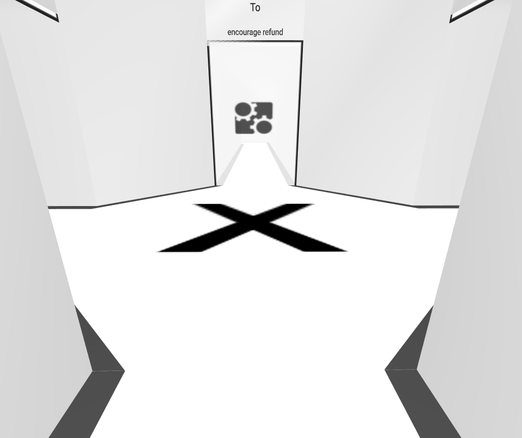
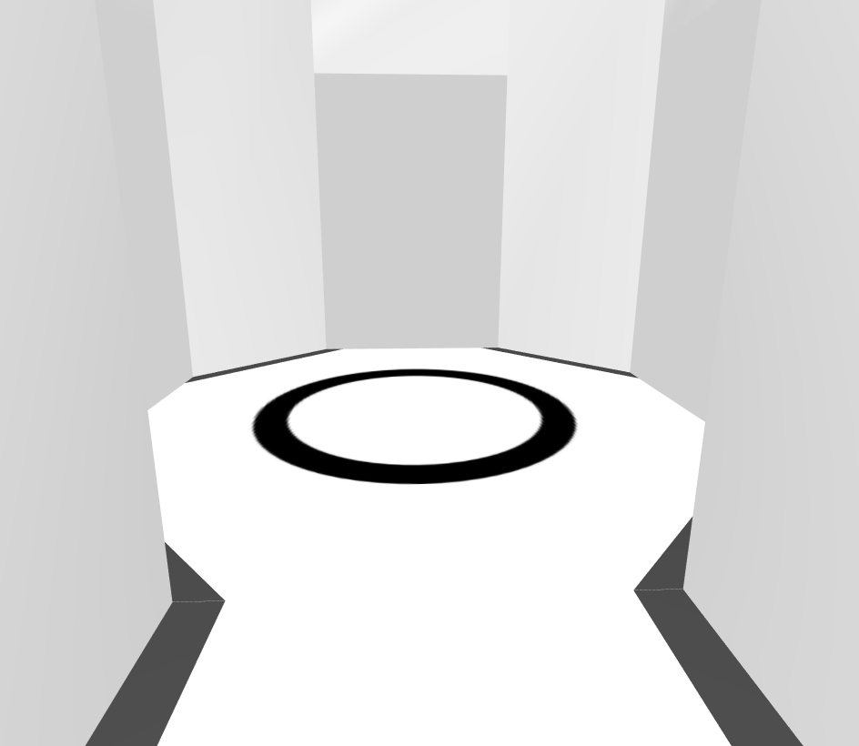
While task rooms are large and rectangular in shape, gateways and events are much smaller. There still needs to be a connection for the sequence flows, giving the element an octagonal shape:
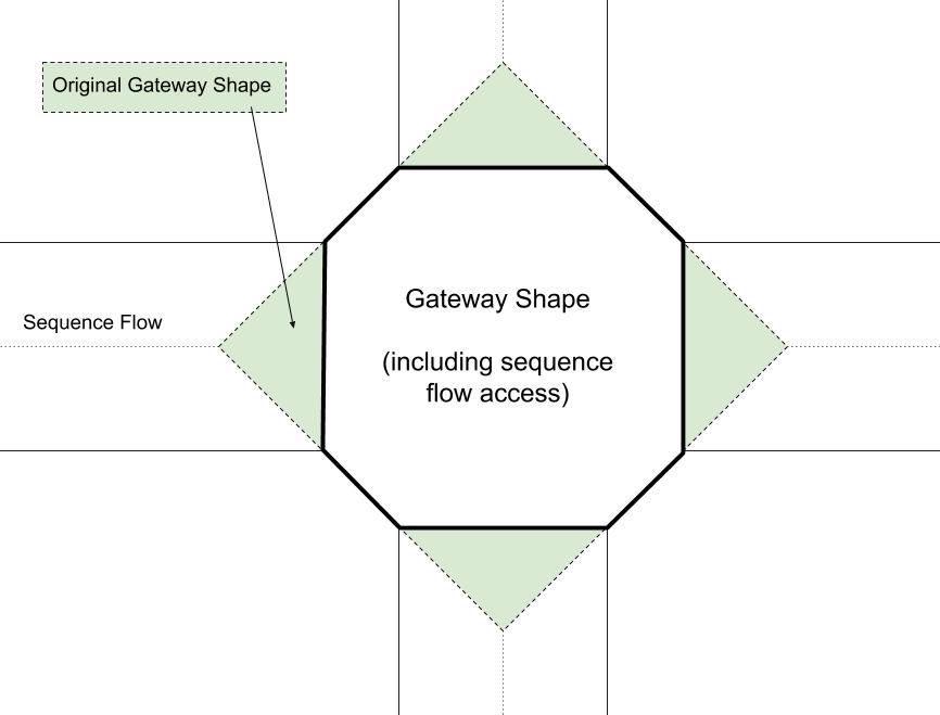
Like tasks, gateways and event have doors for connecting sequence flows and intransparent images covering unused sequence flow connections. You can find the source code that created the vertices faces, images on the ground, doors and door-covers here.
Source Code and Further Reading
This post only covers the basics of what goes on behind the scenes of “Be A Token”. There are lots of aspects that are required, like player movement, collision detection, door labels and much more. If you are interested in that, you can check out the source code of “Be A Token” on GitHub. You can also use the online version of “Be A Token” to move through a sample process yourself.
