There are multiple angles to look at workflows one of which is patterns. The Workflow Patterns initiative differentiates between control, data, and resource perspectives. They are not just focusing on the modeling language as such but have workflow systems in mind too. It’s valuable to have a closer look at those patterns and discuss which parts of it can be shown and even automated in BPMN, and which parts are taken care of in the technical implementation. I have seen BPMN diagrams that try to include every aspect in the diagram itself. This often leads to overloaded BPMN models with a lack of clear transparency of the business flow. Therefore, it is important to focus on all aspects of workflow patterns differently. In this blog post, I will discuss the differences between technical implementation and modeling by reference to the patterns of the Workflow Pattern initiative.
Besides patterns defined by the Workflow Patterns initiative that focuses on workflow systems and technical implementation, there are also patterns on the modeling level. Situation patterns are parts of workflows that are used across different industries. They focus on BPMN elements and outline how to model those situations. By far, my favorite patterns are Anti-patterns. Those outline how you should not model and are the counter-answer to best practices.
This blog post presents, for each pattern, a BPMN workflow diagram example and discusses how in BPMN, different principles are implemented. It also focuses on parts that belong to the technical implementation and don’t need to be shown in the BPMN diagram itself. First, we look at the patterns from the Workflow Patterns initiative and the last two patterns will focus on patterns tackling the modeling layer.
Workflow diagrams and the control pattern
In general, the idea of workflow control patterns describes the process flow. Control patterns outline the order in which activities are handled. It deals with parallelization, exclusive and inclusive decisions, and so on. These words might already trigger the picture of different BPMN gateways in your head, which are an important part of it. But there are more complex and advanced patterns described too. Often advanced patterns require simple patterns.
Let’s have a look at control pattern number 16: Deferred Choice. The branches in a workflow are chosen based on external interaction with the operating system (workflow engine).
Example:
“At the commencement of the Resolve complaint process, there is a choice between the Initial customer contact task and the Escalate to manager task. The Initial customer contact is initiated when it is started by a customer services team member. The Escalate to manager task commences 48 hours after the process instance commences. Once one of these tasks is initiated, the other is withdrawn.”
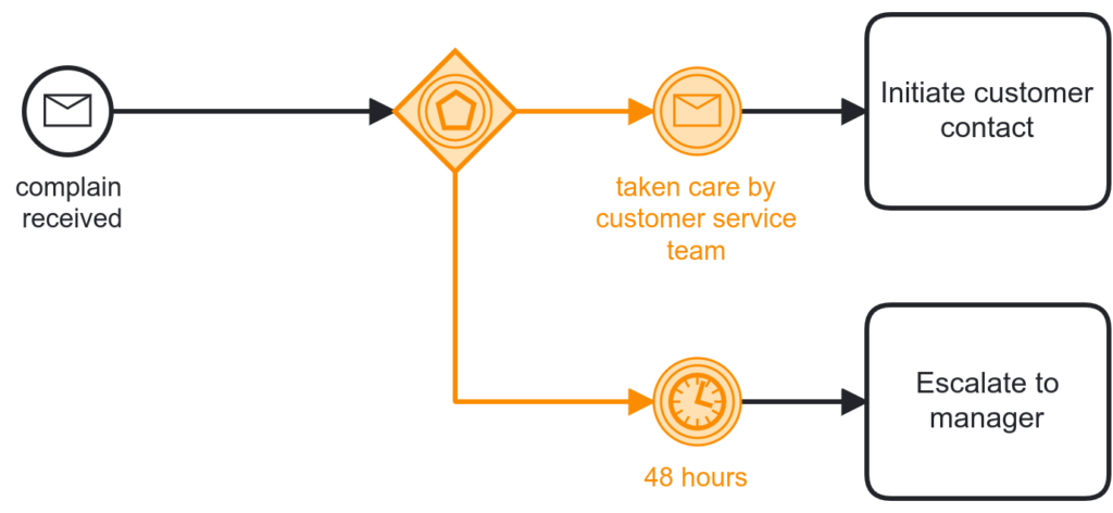
The diagram above outlines the process part from the given example. The event-based gateway is used to describe the racing condition that is based on external factors. Either a message arrives, or there will be a timer triggered once 48 hours pass.
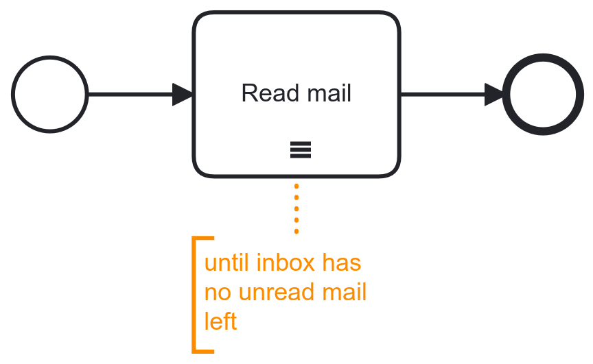
When it comes to the control flow, it is a good idea to have the patterns visible in the process diagram. It is an indicator of the process logic and the execution of the tasks. Nevertheless, technical implementation can be important too. Especially if we talk about multi-instances. In the diagram below, we see a multi-instance task. We can use annotation and some text information to indicate the condition or cardinality for a multi-instance activity, but the implementation itself happens on a technical level. Even though for the automation of a multi-instance activity, we don’t need the annotation, it is bad practice to leave it out. If you leave it out it is not clear for the reader of a diagram how often an activity is executed.
There are more control patterns to discover. We have some more examples of advanced control patterns for process automation. This is a create ressource that explains why advanced control patterns make sense for workflow automation and outlines how BPMN can enable development teams by providing transparency among the control flow.
Workflow diagrams and the data pattern
The idea around the data perspective is focused on how information is passed and how variables are handled. The BPMN 2.0 standard uses the datastore and the data object for this. Let’s have a look at data pattern number 15, which describes pushing data from a task to an external data source for permanent storage. The given example is:
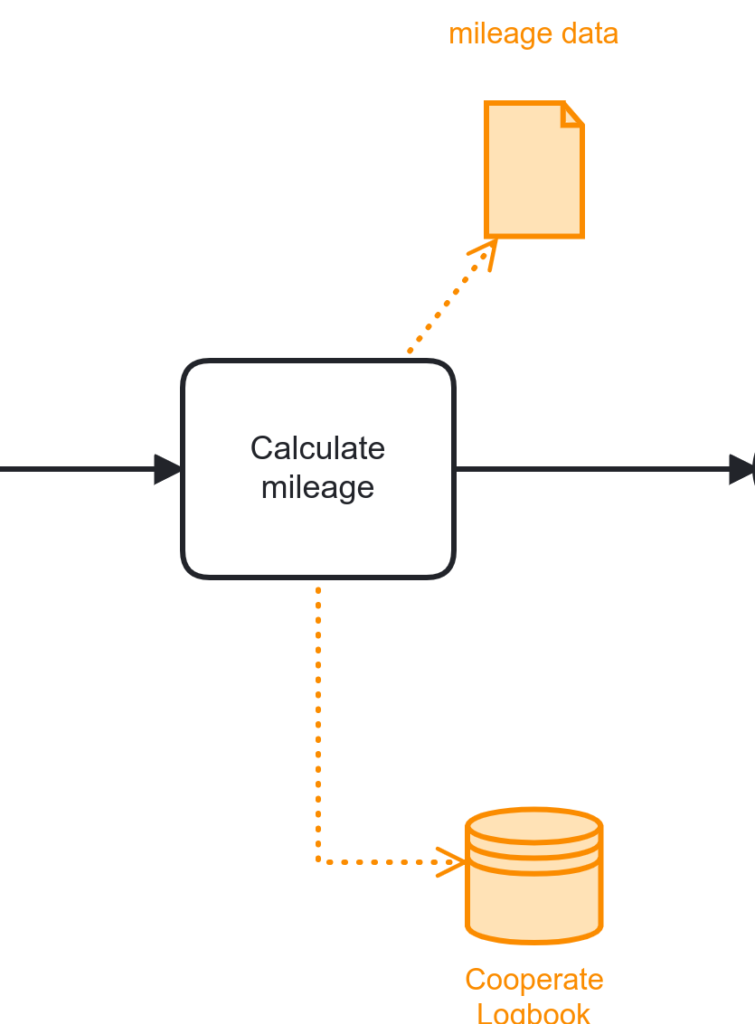
“The Calculate Mileage task passes the mileage data to the Corporate Logbook database for permanent recording.”
In the BPMN diagram below, the data storage represents the corporate logbook. The data storage in BPMN symbolizes permanent data. Data symbols are connected with data flows. The direction of the arrow outlines that data is pushed to the data storage. The data object symbolizes the mileage data. Data objects outline which data is produced during a certain task and which data is consumed by certain tasks, which is determined by the direction of the data flow arrow.
Another way to visualize the interaction with an external system can be to model the logbook as a collapsed pool with a message flow attached.
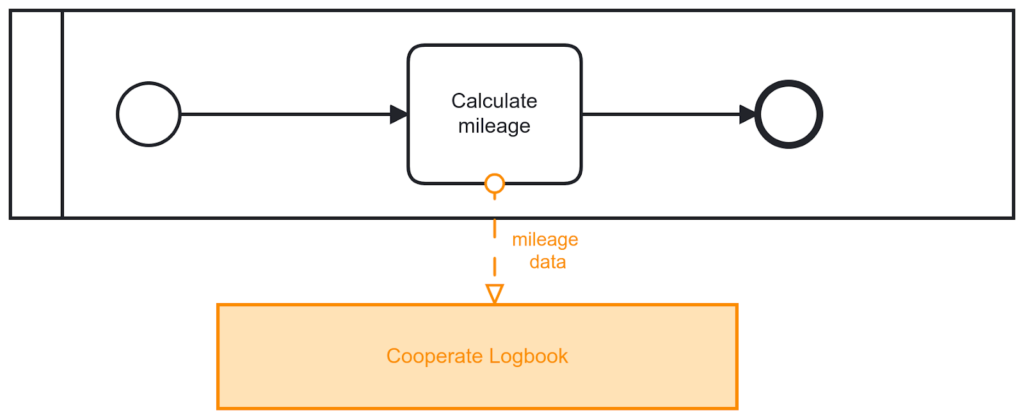
One important thing to notice is that the data flow and the message flow in BPMN don’t have any automation semantics attached to it. So this should just be considered for documentation and has nothing to do with implementing such a workflow. Hence when looking at BPMN, it is always important to look at the technical implementations capacities of the workflow engine implementing the diagram. Looking at Camunda’s workflow technologies concepts around variables and data types in general, variables scopes, and input and out variables mapping. Additionally, APIs to connect to external systems are important.
Looking at the different data patterns from the workflow initiative, you can always use the data storage, and the data object to give additional information to the reader. Normally that is enough to understand how the business process treats important business data. Still, in some cases, more complex data patterns might miss some fine granularity in BPMN – and that is okay- BPMN as a language should focus on the business process and its flow. I would recommend only using data symbols where it is necessary to understand business logic, but I would not model each implemented process variable. This overloads the model and can hide away the business flow. Hence when it comes to data patterns in workflows, it is necessary to look at the technical implementations and capabilities of workflow engines.
Workflow diagrams and the resource pattern
The resource pattern is another interesting topic. Resource patterns describe who is responsible for certain tasks. This can be human or non-human resources. In BPMN, the human resource relates to the User Task and the Manual Task. BPMN describes a detailed user task lifecycle. Similar to handling data in BPMN, handling human resources can be symbolized in BPMN but has no execution logic behind it. To outline different roles, you can use the pool with different lanes. For non-human tasks, BPMN provides different task types. So every task type that is not a User or a Manual task is a non-human task, for example, the Service and Script Task. Other than for human tasks, lanes in BPMN are not designed for using it with non-human tasks. If you see a BPMN diagram where a system is having an own lane, this is an Anti-Pattern (I will talk about those later in this post). System interaction can be outlined by using the data storage or with collapsed pools with message flows, as discussed in the paragraph about data before.
Let’s have a look at the pattern that describes the role-based distribution. The example states: “Instances of the Approve Travel Requisition task must be executed by a Manager.”
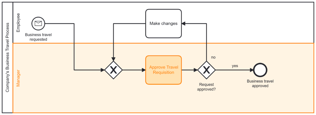
There are boundaries when it comes to resource visualization in BPMN. Imagine you want to express that a single task can be handled by two different roles. You can’t expand a task over two lanes. You could now create a new lane that includes both roles. By doing so, you would overload your BPMN diagram. Additionally, including many lanes often hides the happy path of your business process. This can sometimes lead to an Anti-Pattern. The idea of the happy path is that it is on the top branch, which you read from the left to the right. This gives the reader a clear idea of what the desired outcome of the process is. If you use multiple lanes, it is not possible anymore to model the happy path linear from the left to the right because by introducing lanes, the sequence flow has to go up and down as well. The post will talk about Anti-Patterns in more detail later.
Resource patterns go beyond simple task allocation by department or role. It is important to evaluate those patterns in combination with the technical implementation details of workflows. It is important to understand concepts around task allocation and other mechanisms. For example, if you want that the same person that handled task A should also handle task B, it is important to evaluate if dynamic task allocation via expressions is possible.
Workflow diagrams and situation patterns
Let’s switch to patterns that focus on the modeling layer. Situation patterns are well known in this area. Those patterns describe parts of a workflow that happen in different organizations and are not business specific. Other than a control flow, there is already some business logic attached to it. A very common example is the 4-eye-principle (also known as requiring a second set of eyes). But there are more situation patterns to discover. There are often multiple ways to express them in BPMN. Which one to choose can depend on the additional business context or modeling practices and guidelines in your organization.
An example of a situation pattern is the cancellation of a process based on external input. There are multiple companies across industries that interact with customers (external and internal ones). Here are some examples:
- During an order process, a customer can cancel the purchase.
- By opening an insurance recourse procedure, the assured person can disagree.
- A contract won’t be signed, and the customer cancels the deal.
Obviously, in the described examples, the cancellation might lead to different business logic and models afterward. The idea of the pattern is that the workflow can be canceled by an external party (we can consider other departments within the same company as external too, because the business process is owned and operated by another business unit).
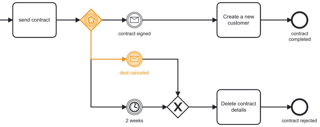
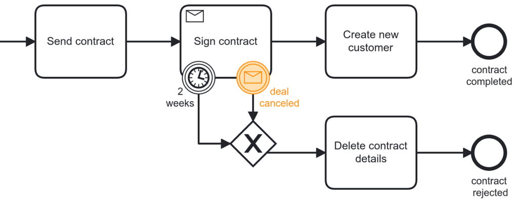
To trigger the cancellation from an external party, we can use an intermediate message catch event. Based on that, we have multiple options to react in BPMN on such messages:
1) We can consider the possibility of the cancellation at a specific point in the process. If cancellation is just possible at a specific point in the process (normally when we wait for a confirmation, answer, etc.), event-based gateways or attached boundary events are symbols to choose from.
Example with event-based gateway:
Example with the attached-boundary event:
2) If the cancellation is possible at multiple points, we can scope those points. In BPMN, we can scope parts of the process using collapsed subprocesses. Within that scope, we have different options again. We can use attached boundary events, or we can also use event subprocesses.
Example with subprocess and attached boundary event:

Example with event subprocess:
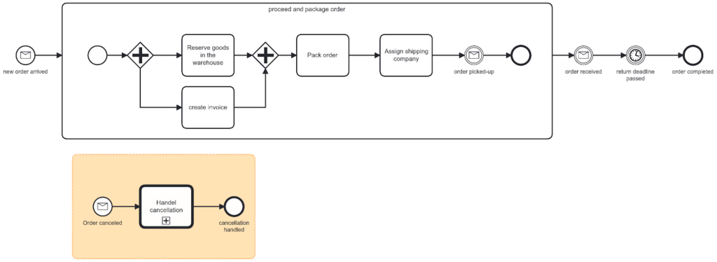
One important note here is that the example with the event subprocess allows you to cancel the order at any time of the process. The overall scope here is the process itself. Therefore the execution logic of the two models in this section is not identical. In the process with the event-based gateway, it is not possible to cancel the order at the time when the shipping service is sending the items. It is only possible before the shipping company picks up the order or after the order is received by the customer. If you want to express that cancelation is always possible, the event subprocess is the best option. It is another Anti-pattern if you create a start and end event and in between is a subprocess with attached boundary events.
Workflow diagrams and Anti-patterns
One of my favorite kind of patterns are Anti-patterns. I hope no one uses them in production. Anti-patterns add some mysticism to your diagrams. Normally, Anti-patterns are the opposite of modeling best practices and make it harder to read a BPMN diagram. What do I love about them? Debugging them and adding the best practice to them!
In terms of technical implementation and process flow, the tricky thing is that they just work. So, just because a model runs in production does not mean it is a good process model. Here is one example: BPMN’s best practice is to model from left to right. The Anti-pattern to that best practice? Modeling from top to bottom:
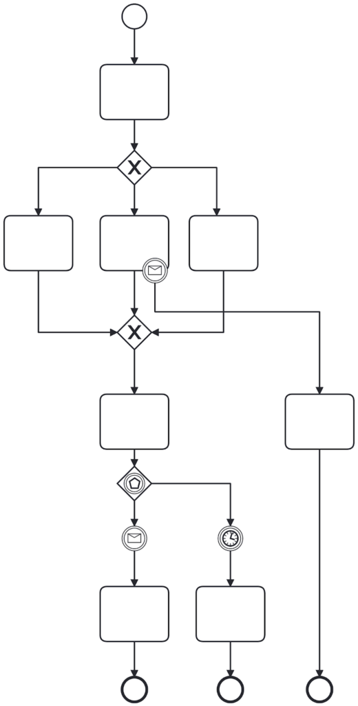
The problem is that BPMN is designed to be modeled from the left to right. For example, if you include lanes, the concept from the top to the button is not working. Further, it is harder to outline external communication with collapsed pools. And even if you don’t use pools and lanes, the happy path is not visible if you model from the top to the bottom.
But it can be even worse. Some models remind me of the game Snake. It looks like the canvas has a limit, and the person who modeled the process tried their best to get everything into the canvas. Maybe they haven’t figured out how to zoom in and out, or they wanted everything printed on one A4 page?
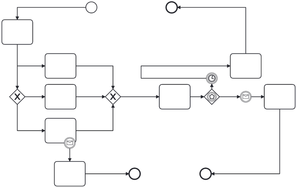
Okay, because we saw the Anti-pattern, let’s finish this blogpost with doing it right:
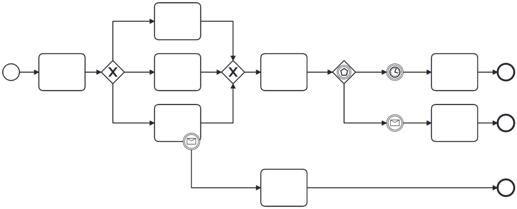
The visualization of Anti-patterns together with the best practice can help us to understand why Anti-patterns are harder to read and tell us what we should avoid while modeling. In the case above we can clearly see the process flow and the happy path. In the model above we see that the happy path after the event-based gateway continues with the timer event. The outline gets clearer and it is easier to read the model and get a quick overview of it.
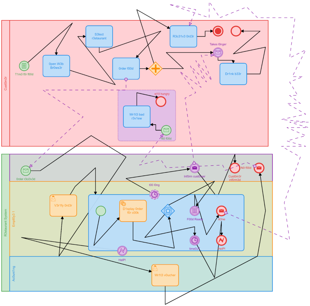
If you combine multiple Anti-Patterns like using lanes, no good layout, and colors you can create artwork to enrich the life of your co-workers with the danger that no one understands the process anymore. This said I like to finish the post with some art for you:
Conclusion
The post outlined five patterns that exist when we look at workflow diagrams. It outlined the different concepts that exist with BPMN to deal with control flows, data, and resources. Besides the modeling, it underlined the aspects of automation too. Further, I discussed the modeling layer Situation and Anti-patterns. So now it is time for your own art … ahhh, I mean … workflow diagram using BPMN. You can sign up for Camunda 8 and get started right away. Make sure to read our modeling best practices. If you want to become a full BPMN expert you can take our free BPMN online course.
Any questions? Find us in the forum. I am looking forward to seeing your workflow diagrams and questions there.
